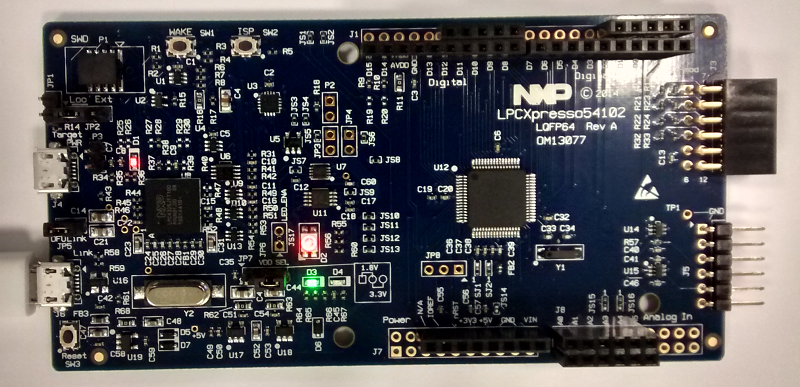
Yesterday I received a brand new LPCXpresso54102 evaluation board, and after playing with it for a while and going through the documentation, I thought it could be useful to write down how to set up the environment and work around a few quirks that I found are not completely straightforward.
The board contains the new LPC54012 ultra-low-power dual-core ARM Cortex-M4F/M0+ microcontroller, targeted at always-on sensor-processing applications, that can run up to 100Mhz each core. The main idea is to use the Cortex-M0+ core for sensor listening, data collection and aggregation, and then wake up periodically the Cortex-M4F to perform complex data processing tasks.
Like all the LPCXpresso boards, it comes also with an integrated LPC-Link2 debugger that can be used to debug the on-board processor as well as an external target. This is the first board of the LPCXpresso V3, and the debugger includes two modes: the new standard CMSIS-DAP and the propietary RedLink protocol.
Installing LPCXpresso IDE and LPCOpen examples
LPCXpresso IDE and board drivers
First you need to get and install the multi-platform Eclipse-based LPCXpresso IDE, or if you have it already be sure that it is at least v7.5.0. The software is free of charge up to 256KB of code, which is very nice compared to the 32KB limit of other proprietary tools. You will need to register (free) in the website and get an activation key to get all the features. After this, you will have to download and install the LPC-Link2 USB drivers before plugging in the board.
LPCOpen examples and libraries
LPCOpen is a set of C libraries for fast development that is compatible across all the range of NXP ARM-based LPC microcontrollers with a common API, and includes graphic libraries (emWin/SWIM), a USB (LPCUSBLib) and networking stack (LWIP), and a FreeRTOS package, among other things.
Since this family is very recent, the LPCOpen package for the LPC5410x is not yet included in the LPCxpresso installation, but you can get it here. I suggest copying first the .zip file into the folder C:\nxp\LPCXpresso_7.5.0_254\lpcxpresso\Examples\LPCOpen (or in the Examples\LPCOpen folder wherever you have installed your LPCXpresso IDE), so you have all the LPCOpen packages in the same place.
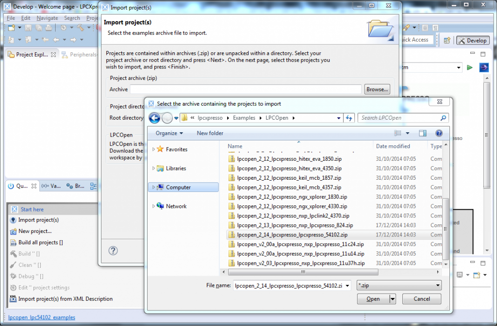
After this, just click on the Import project(s) wizard on the bottom left side panel, select the lpcopen_2_14_lpcxpresso_lpcxpresso_54102.zip file and import all the projects to the workspace.
There are four projects imported that are actually the LPCOpen chip and board support libraries: lpc_board_lpcxpresso_54102, lpc_board_lpcxpresso_54102_m0, lpc_chip_5410x and lpc_chip_5410x_m0.
Debugging a Cortex-M4/M0+ application
CMSIS-DAP vs. RedLink debugging
For debugging, the board has to be powered through the microUSB connector J6. If the jumper JP5 is removed, the debugger works with the CMSIS-DAP mode. That includes several features through the same connection: standard CMSIS-DAP debugging, serial Virtual COM emulation, and the new LPCSIO I2C/SPI/GPIO bridge. With the jumper on, it works with the RedLink protocol. It is strongly recommended to put the jumper JP5 and use RedLink protocol, since it will allow us to do multicore debugging.
The boot process
Both cores can work completely independent from each other, but the boot process is handled by the on-chip boot ROM and is always executed by the Cortex-M4F core. After the bootloader and system init section, it is the job of the Cortex-M4F to set up the environment for the Cortex-M0+: provide a reset handler and stack pointer address for the Cortex-M0+, and take it out of reset. Therefore, if you are planning on using the Cortex-M0+ (alone or simultaneously with the Cortex-M4F), it is always necessary to have a valid image for the Cortex-M4F that at least prepares and wakes up the Cortex-M0+ before putting himself to sleep.
You can see an overview of the boot process in the following image, extracted from the AN11609 Dual Core application note:
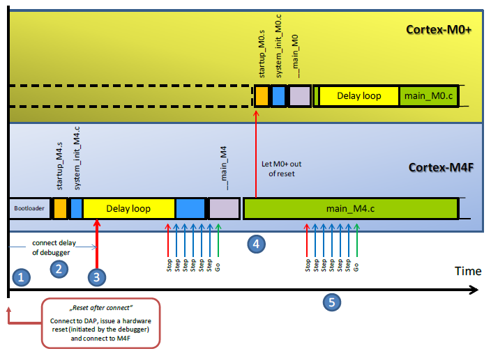
The delay loop is a soft delay that prevents the code to run into complex application code before the debugger is able to get the core and stop it, but it is not strictly necessary and can be avoided inserting a break point in the correct place.
Multicore debugging
Although both binaries can be combined into one, it is easier to just have two projects and two images separately, and to debug both at once. We will use the multicore blinky example to setup a multicore debugging session. This example blinks intermittently green and red the RGB LED. The Cortex-M4F acts as the master and the Cortex-M0+ as the slave, sharing the state of the LED through a hardware mutex and communicating by means of a mailbox mechanism (have a look at the readme.txt in the src folder for more detailed information).
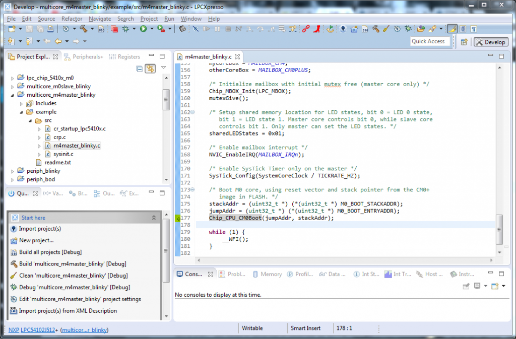
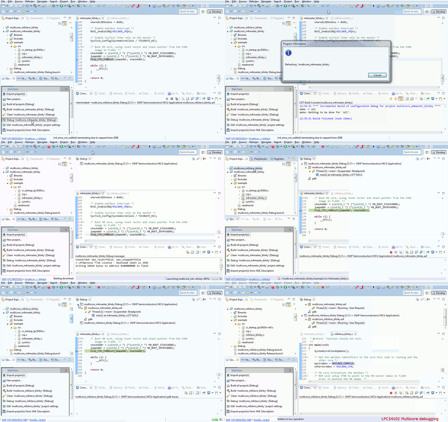
First, open the m4master_blinky.c file in the multicore_m4master_blinky project and set a break point in the Chip_CPU_CM0Boot() line in the main (double clicking on the left side).
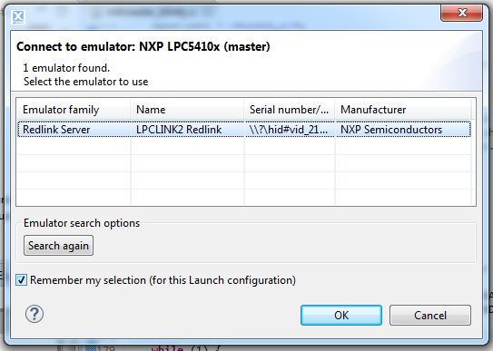
Now plug in the board and click on the Debug ‘multicore_m4_master_blinky’ [Debug] command in the bottom left panel. After compiling, it will prompt you to select the LPCLINK2 Redlink emulator.
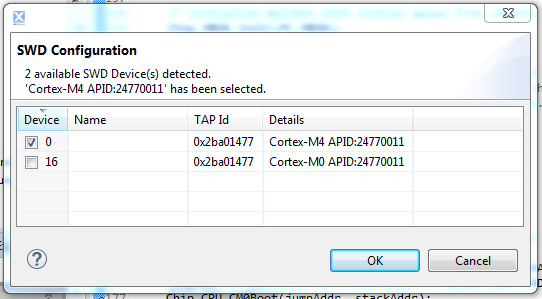
Then you have to select one of the two SWD device availables, in this case the Cortex-M4.
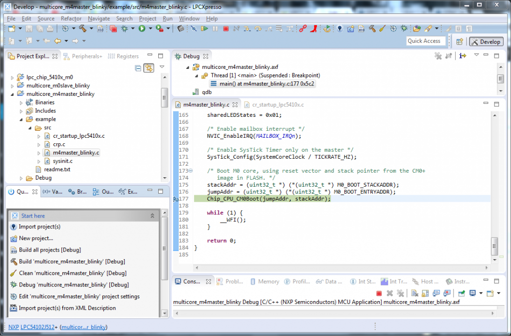
After clicking on the green button on the top bar (Resume), the debugger will stop at the Chip_CPU_CM0Boot() line at will be ready to start debugging the other core.
Next, select the multicore_m0slave_blinky project and click on the Debug ‘multicore_m0_master_blinky’ [Debug] command.
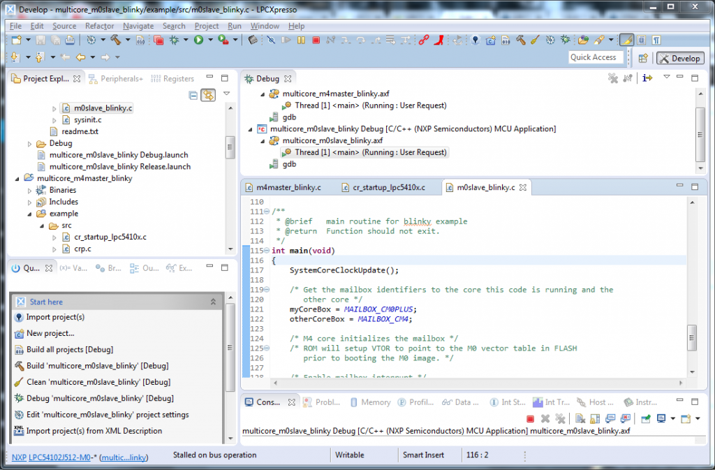
After building the project and selecting the Cortex-M0 SWD configuration (the only one available at this moment), the second debug session is ready to run automatically in ‘attach only’ mode, ready to start running after you click the Resume button again for the Cortex-M4 debug session. After resuming the Cortex-M4, the Chip_CPU_CM0Boot() function wakes up the Cortex-M0+ core and its debugging session pops up at the main(), waiting for you to click resume again and finally have both cores running thorough the debugger at once. If everything is correct, you will see the red/green LED blinking in your board.
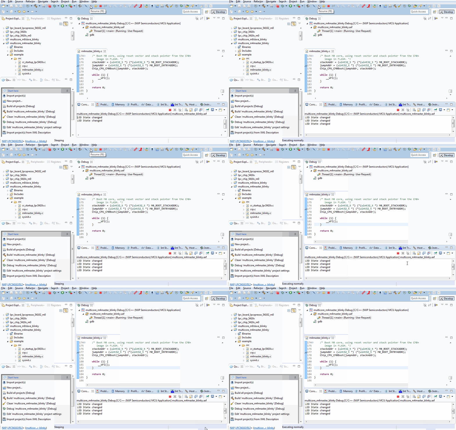
Here it is an animation of the process.
Adding string debugging semihost support
The SWD protocol has a nice feature that allows redirecting the printf() to the SWO pin, so that you can output string data to the LPCxpresso console withouth the need of a Virtual COM port. For this, it is necessary to use a libc implementation that supports semihosting. Fortunately, LPCXpresso and LPCOpen come prepared for this, you just need to enable it and select the correct library.
We are going to add string support for the Cortex-M4F. First we need to open the board.h file inside the inc folder of the lpc_board_lpcxpresso_54102 project, and uncomment the #define DEBUG_SEMIHOSTING line. For the Cortex-M0+ would be the same, but from the lpc_board_lpcxpresso_54102_m0 project.
Next, click right button on the multicore_m4slave_blinky project, properties. From C/C++ Build > Settings > MCU Linker > Managed Linker Script change the parameter Library to Redlib (semihost).
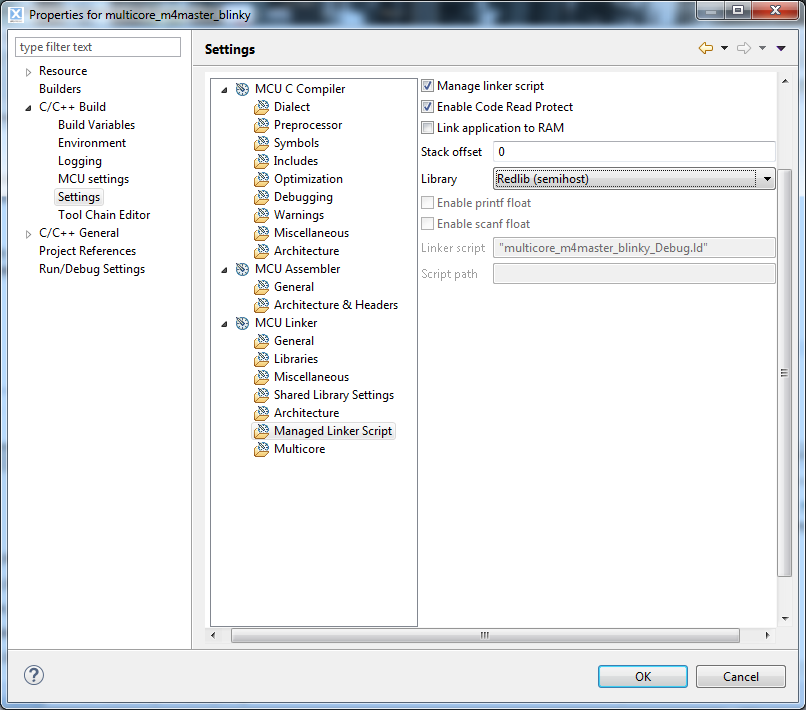
Now we can use the DEBUGOUT() macro to print messages to the console. We are going to add the line DEBUGOUT(“LED State changed\n”); insde the updateLEDStates function, to show a message each time the LED blinks. Now clean the project, rebuild it and run a debug session. Be aware that this puts a heavy load on the debugging, and can mess up the timings on your program, so use it sparsely. Also, when the program is free running without a debug session, it will not work correctly if there are debug messages, so do not forget to comment out the #define DEBUG_ENABLE line in the board.h before compiling if you are going to test it outside the debugger.
Creating a new Cortex-M4F project
Using the LPCxpresso wizard is easy to create a new project from scratch. We start clicking on New project… button at the bottom left panel, and selecting an LPCOpen Project for LPC5410x (M4).
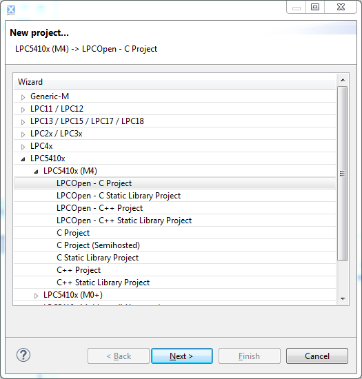
Give it a name and select the LPC54102J512 MCU. The LPCOpen chip and board libraries are already imported to the workspace, therefore you just need to select them and click next.
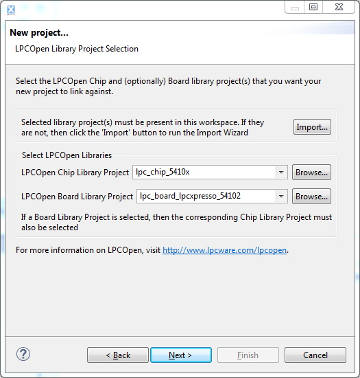
If you want to use the CMSIS DSP Library, which comes with a good batch of math functions (FFT, statistics, etc.), add them now clicking import and selecting the CMSIS_DSPLIB_Latest.zip file.
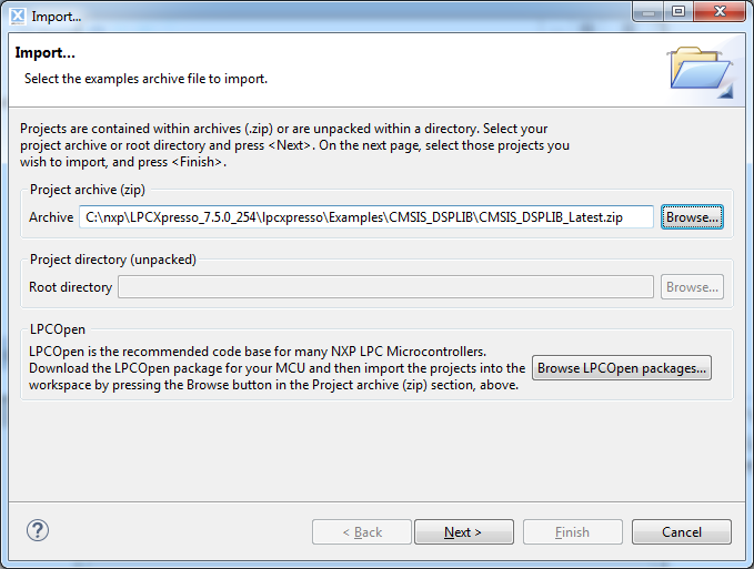
After importing, select CMSIS_DSPLIB_CM4 as the CMSIS DSP Library to link project to. Click Next, keep checked the Enable RAM banks disabled by default option. For now, leave the Enabled_SoftABI option for the FPU to avoid problems, and the rest of the options checked as they are by default.
Now we can remove the while(1) loop and change it for the following code, to configure the SysTick Timer and put the core to sleep:
/* Enable SysTick Timer */ SysTick_Config(SystemCoreClock / 10); while (1) { __WFI(); } |
And add the interrupt handler function before the main():
void SysTick_Handler(void) { Board_LED_Toggle(0); } |
Finally, click Debug and you will see the red LED flashing at 10Hz.
In a future post I will try to explain how the mailbox system works for communicating and sharing data between cores, as well as how the LCPCSIO I2C/SPI/GPIO to PC bridge is used, when more documentation becomes available.
Very nicely explained.
I especially liked your description of the dual core booting sequence.
Carmelo.
Well done. I had the same board and I went through the same demonstration by the NXP FAE, and on some cases the LPCexpresso was making some problems when debugging both core using the same instance of the debugger.
Did you had the same behavior?
Anyway nice work. Sash
P.S. nice WP theme
Yes, it gives problems sometimes, like for instance not starting or stopping one the cores, it is something they still have to improve. That is why I think mbed won’t be coming to this processor any time soon, at least for dual core operation.
Thanks, I designed the theme myself from scratch, I wanted something simple.
Hi David,
Very helpful post, thank you. And are you still planning to post about how the mailbox communication works?
Can u explain how to do the IR remote controlling using LPC54102Xpresso??